The Working Principle of a strain gauge load cell
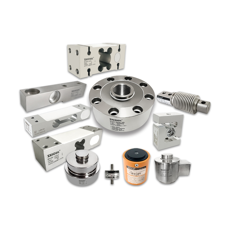
A load cell is a transducer that measures force, and outputs this force as an electrical signal. Most load cells use a strain gauge to detect measurements.
In general, an electrical strain gauge is nothing more than a measuring instrument capable of detecting deformations, even minimal, of a material subjected to mechanical or thermal stress. Through the detection of deformations it is possible to obtain the load to which the material is subjected.
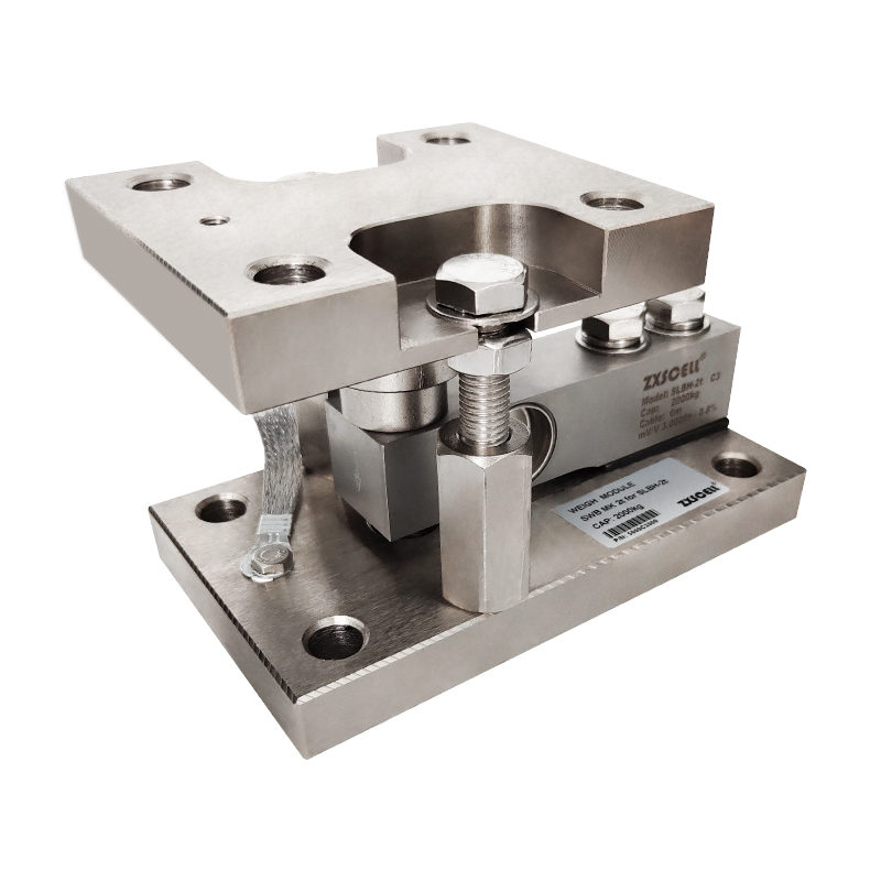
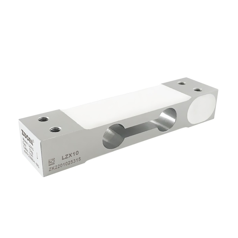
The load cells with electrical strain gauges are therefore composed of a metal body on which electrical resistances, the real strain gauges, are glued. When the load is applied, the metal deforms, changing the electrical resistance of the applied strain gauges.
On average, each load cell is equipped with four or eight strain gauges, connected together in a Wheatstone bridge configuration fed at constant voltage on a diagonal. The bridge supplies, on the second diagonal, a signal proportional to both the supply voltage and the resistance variation of the strain gauges. The latter is caused by the applied load, which has deformed the metal.
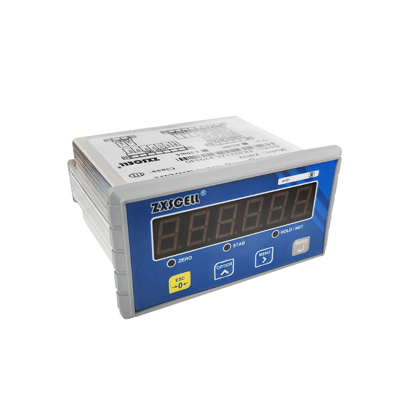
Therefore, a signal expressed in mV / V will be provided at the output, one milliVolt for each supply Volt.
In order for the strain gauge bridge to be accurate it is necessary to integrate it with the following auxiliary circuits:
1. Bridge zeroing circuit: allows for a zero output when no load is present;
2. Zero drift compensation circuit: it allows to neutralize the variations of the elastic modulus caused by the temperature changes at zero load;
3. Field drift compensation circuit: similar to the one above, this circuit neutralizes the variations of the elastic modulus related to the temperature changes during the load;
4. Output signal calibration circuits: make the signal stable through the use of high stability resistors in series with the power supply voltage;
Finally, it should be noted that the output signal calibration circuits and the field drift compensation circuits must necessarily be divided symmetrically throughout the power supply circuit to avoid the circulation of eddy currents when using systems with multiple cells of load.